Thursday 21 February 2019

Effects Arises due to Voltage Unbalance

Unbalanced systems indicate the existence of a negative sequence that is harmful to all poly phase loads, especially three-phase induction machines.


The main effect of voltage unbalance is motor damage from excessive heat. Voltage unbalance can create a current unbalance 6 to 10 times the magnitude of voltage unbalance. In turn, current unbalance produces heat in the motor windings that degrades motor insulation causing cumulative and permanent damage to the motor. 

This scenario would result to expensive facility downtime due to motor failures.

The graph below shows the relationship between voltage unbalance and temperature rise, which approximately increases by twice the square of the percent of voltage unbalance.


  1. Increased current loading and losses in the network.
  2. With equal load power the phase currents can attain 2 to 3 times the value, the losses 2 to 6 times the value. It is then only possible to load lines and transformers with half or one third of their rated power.
  3. Increased losses and vibration moments in electrical machinery.
  4. The field built up by the negative sequence component of the currents runs against the phase sequence of the rotor and therefore induces currents in it, which lead to increased thermal loading.
  5. Rectifiers and inverters react to unbalance in the power supply with uncharacteristic harmonic currents.
  6. In three-phase systems with star connection, current flows through the neutral conductor.

For Advanced Power  Quality products Study & Completely Automated Report:  

Connect with Emerich Energy Please write to us info@emerich.in  Call: 044-48577667

Please subscribe our blog https://blog.emerich.in/
Follow us LinkedIn   https://www.linkedin.com/company/emerichenergy/ 

Basics of Voltage Unbalance - Causes & Sources

The electrical power issues that most frequently affect industrial plants include voltage sags and swells, harmonics, transients, and voltage and current unbalance.

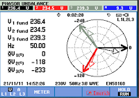
Voltage Unbalance (or Imbalance) is defined by IEEE as the ratio of the negative or zero sequence component to the positive sequence component. In simple terms, it is a voltage variation in a power system in which the voltage magnitudes or the phase angle differences between them are not equal. It follows that this power quality problem affects only poly phase systems (e.g. three-phase).

Voltages are rarely exactly balanced between phases. However, when voltage unbalance becomes excessive, it can create problems for poly phase motors and other loads. Moreover, adjustable speed drives (ASD) can be even more sensitive than standard motors.

Voltage unbalance is primarily due to unequal loads on distribution lines or within a facility. In other words, the negative or zero sequence voltages in a power system typically result from unbalanced loads causing negative or zero sequence currents to flow.

In a balanced three-phase system, the phase voltages should be equal or very close to equal. Unbalance is a measurement of the inequality of the phase voltages. Voltage unbalance is the measure of voltage differences between the phases of a three-phase system. It degrades the performance and shortens the life of three-phase motors.

Effects of Unbalance

Voltage unbalance can cause three-phase motors and other three-phase loads to experience poor performance or premature failure because of the following:
  • Mechanical stresses in motors due to lower than normal torque output.
  • Higher than normal current in motors and three-phase rectifiers.
  • Unbalance current will flow in neutral conductors in three-phase systems.

Voltage unbalance at the motor terminals causes high current unbalance, which can be six to 10 times as large as the voltage unbalance. Unbalanced currents lead to torque pulsation, increased vibration and mechanical stress, increased losses, and motor overheating. Voltage and current unbalances could also indicate maintenance issues such as loose connections and worn contacts.

Unbalance can occur at any point throughout the distribution system.Loads should be equally divided across each phase of a panel board. Should one phase become too heavily loaded in comparison to others, voltage will be lower on that phase. Transformers and three-phase motors fed from that panel may run hotter, be unusually noisy, vibrate excessively, and even suffer premature failure.

How measure unbalance

You can make some basic phase-to-phase voltage unbalance measurements using a high-quality Digital Multi Meter and phase-to-phase current unbalance using a high-quality clamp meter. Accurate, real-time unbalance measurements need a three-phase power quality analyzer to enable solving unbalance problems. Open circuits and single-phase to ground faults are easier to correct than load balancing, which typically requires corrective system-level design changes..

In reality, voltage differences between phases vary as loads operate. However, motor or transformer overheating, or excessive noise or vibration, can merit troubleshooting for voltage unbalance. Monitoring over time is the key to capturing unbalance. In a three-phase system, the maximum variation in voltage between phases should be no more than 2 percent (the V neg % value on the analyzer), or significant equipment damage can occur.

Causes & Sources

General

The utility can be the source of unbalanced voltages due to malfunctioning equipment, including blown capacitor fuses, open-delta regulators, and open-delta transformers. Open-delta equipment can be more susceptible to voltage unbalance than closed-delta since they only utilize two phases to perform their transformations.  

Also, voltage unbalance can also be caused by uneven single-phase load distribution among the three phases - the likely culprit for a voltage unbalance of less than 2%. Furthermore, severe cases (greater than 5%) can be attributed to single-phasing in the utility’s distribution lateral feeders because of a blown fuse due to fault or overloading on one phase.

Motors

The facility housing the motor can also create unbalanced voltages even if the utility supplied voltages are well balanced. Again, this could be caused by malfunctioning equipment or even mismatched transformer taps and impedance. Similar to the utility, poor load distribution within the facility can create voltage unbalance issues.

The motor itself can also be the source of voltage unbalance. Resistive and inductive unbalances within the motor equipment lead to unbalanced voltages and currents. Defects in the power circuit connections, the motor contacts, or the rotor and stator windings, can all cause irregular impedances between phases in the motor that lead to unbalanced conditions.

References:
ANSI C84.1-2006
Dugan, R., McGranaghan, M., Santoso, S., and Beaty, H.W. (2004). Electrical Power Systems Quality (2nd ed.). New York: McGraw-Hill.
IEEE 1159-1995. Recommended Practice For Monitoring Electric Power Quality.
National Electrical Manufacturers Association (NEMA) Publication No. MG 1-1998 Motors and Generators

For Advanced Power  Quality products Study & Completely Automated Report:  

Connect with Emerich Energy Please write to us info@emerich.in  Call: 044-48577667

Please subscribe our blog https://blog.emerich.in/
Follow us LinkedIn   https://www.linkedin.com/company/emerichenergy/ 

Monday 18 February 2019

VFD - Variable frequency drive Advantages & Disadvantages


Variable Frequency Drive(VFD)is a system that regulates the rotational speed of a motor by controlling the input supplied to it. VFD’s can also be known Adjustable Frequency Drives(AFD) or Variable Voltage Variable Frequency Drives (VVVFD).

VFD’s Application:

VFD’s are used in many different applications,the most common include fan blower, and HVAC systems. A VFD can be attached to a fan/blower system to help conserve energy by supplying only the amount of air that the process requires. Variable frequency drives can also be used on pumps, conveyors, and machine tool drives. 

Advantages of Using a VFD

Advantages of a Variable Frequency Drives – The main reason/advantage for implementing a VFD into a system is to save money by reducing the overall system energy being consumed. Along with saving money in energy reduction here are some more advantages of using a VFD in a system.
  • Able to control the processes of the system better, giving the operator a bypass option in the case of an inverter failure.
  • System starts up “softer” than normal, meaning it will decrease the average 6    to 7 up to 20 times inrush current during start up.
  • Saves money on the electricity costs of a system.
  • By better controlling a motor’s speed, life of V-belt and or coupling devices is increased.
  • No appurtenance loss for using this control device in a system.
  • Device can include a breaking feature (Check with manufacturer)
  • Reduces the costs of a system eliminating the need to buy an anti rotational device. 

Disadvantages of Using a VFD

Disadvantages of Variable Frequency Drives – VFD’s, though useful in making a system more efficient also bring with them some disadvantages.

· Upfront cost of a VFD can be relatively high depending on how large your system is.    
· Adding a VFD device may lead to a system resonance at certain speeds, leading to;        

1. Dramatically increased noise
2. Excessive vibration.
· VFD device have been known to shorten the life
· Can reduce the service factor on the motor it’s used on. 
3.Initial Drive Cost
   - Motor Heating at low Speeds
   - Maintenance
   - Induced Power Line Harmonics

However, these disadvantages can be mitigated to an extent by correct application and maintenance as outlined above. A simple calculation of energy savings versus the cost of the drive, its installation and maintenance can guide the decision to install a drive (or not).

For Advanced Power  Quality products Study & Completely Automated Report:  

Connect with Emerich Energy Please write to us info@emerich.in  Call: 044-48577667

Please subscribe our blog https://blog.emerich.in/

Follow us LinkedIn   https://www.linkedin.com/company/emerichenergy/ 

Sunday 17 February 2019

Metals sector inattentive of its power quality losses! Why?

Metals manufacturing plants have a high demand for electrical power, are electric motor intense, have high raw material costs & rely heavily on sophisticated automation and on a skilled labour force.Common to these characteristics is that they all lead to significant operating losses when the electric power is interrupted.


The European Copper Institute (ECI) Power Quality Survey has identified that the metals sector loses over 10% per cent of its net bottom line due to Power Quality operating issues.

The domino effect of production stoppages

Manufacturing plants in the metals sector make generally intense use of electric motors of different ratings and specifications, often integrated in one controlled system. A loss of control of one motor caused by an unexpected and sudden power interruption or power dip can upset the general control and bring the whole production system to a complete standstill. Such an event can, in turn, result in a wide range of financial losses:

Both manufacturing and administrative staff will be made idle when “the lights go out”,often for several hours.

Irregularities in power supply can shorten the useful operating life of expensive high tech machinery or even permanently damage them, resulting in high maintenance and equipment replacement costs.

Raw material that was being processed at the moment of the event can be irrecoverably wasted, or if not will require additional reprocessing to make it again fit for purpose.

Unexpected stoppages play havoc with production planning, resulting in delivery delays, loss of reputation for reliability and consequently loss of business.

Different cost centers blur the reality

The cumulative financial losses caused by power interruptions tend not to be assessed as a totality, relating as they do to different cost centers and occurring at different moments in time.

This might explain why, despite those high potential losses, metal manufacturing sites are on the average not as immune to poor power quality as might be expected. In many of the cases,the total financial waste caused by these interruptions was equivalent to the organisations’ annual electricity bill.

A high price for an under-designed process system

Because of an inadequate power system design, this metals company was being crippled by power interruptions and sudden power reductions causing machinery to fail. In many cases,the precise power quality issue that led to such a breakdown was not known due to a lack of monitoring equipment. The power quality events resulted in production stoppages of 2 hours on average, causing about 300 production staff to be idle. The cost of poor power quality for this company was further exacerbated by raw materials wastage, equipment damage, reduction of operating life time of heavier equipment and the additional maintenance required to get production up and running again.

" Metal industry loses the equivalent of over 50% of its annual electricity bill due to Power Quality losses"

3.4 % of company’s annual turnover being wasted Each time the lamination process in this company was interrupted due to power quality problems, it resulted in high financial losses, consisting mainly of wasted raw materials, low revenues, and staff downtime. Those losses were calculated as equivalent to 3.4% of this company’s annual turnover and to 30% of their net profit.

Understanding the problems – designing the solutions

Emerich Energy Power Quality Survey demonstrates that the majority of the PQ problems faced by the metals sector could be avoided by a more appropriate design of the factory’s own electrical installations. The solutions therefore lie very much in the industry’s own hands. Electrical design engineers involved in this survey recommend a holistic approach to review all the issues at hand, based on three operational pillars:

Correct measurement, to assess the full impact of power quality events, and why they are happening

Appropriate design for the electric installations, ensuring reliability and resilience

Considered investment justified by assessing system renovation cost set against the accumulated losses. 

For Advanced Power  Quality products Study & Completely Automated Report:  

Connect with Emerich Energy Please write to us info@emerich.in  Call: 044-48577667

Please subscribe our blog https://blog.emerich.in/
Follow us LinkedIn   https://www.linkedin.com/company/emerichenergy/ 


Wednesday 13 February 2019

Electrical Enclosure IP Ratings - what they mean?

IP Ratings (Ingress Protection)

A two-digit number established by the International Electro Technical Commission, is used to provide an Ingress Protection rating to a piece of electronic equipment or to an enclosure for electronic equipment.

IP
6
8
“Ingress Protection”First Digit: Solids ProtectionSecond Digit: Liquids Protection

The protection class after EN60529 are indicated by short symbols that consist of the two code letters IP and a code numeral for the amount of the protection.

Example: IP65 

The two digits represent different forms of environmental influence:
 • The first digit represents protection against ingress of solid objects.
 • The second digit represents protection against ingress of liquids.

The larger the value of each digit, the greater the protection. As an example, a product rated IP54 would be better protected against environmental factors than another similar product rated as IP42.

IP TABLE:

IP..First digit:
Ingress of solid objects
Second digit:
Ingress of liquids
0No protectionNo protection
1Protected against solid objects over 50mm e.g. hands, large tools.Protected against vertically falling drops of water or condensation.
2Protected against solid objects over 12.5mm e.g. hands, large tools.Protected against falling drops of water, if the case is disposed up to 15 from vertical.
3Protected against solid objects over 2.5mm e.g. wire, small tools.Protected against sprays of water from any direction, even if the case is disposed up to 60 from vertical.
4Protected against solid objects over 1.0mm e.g. wires.Protected against splash water from any direction.
5Limited protection against dust ingress.
(no harmful deposit)
Protected against low pressure water jets from any direction. Limited ingress permitted.
6Totally protected against dust ingress.Protected against high pressure water jets from any direction. Limited ingress permitted.
7N/AProtected against short periods of immersion in water.
8N/AProtected against long, durable periods of immersion in water.
9kN/AProtected against close-range high pressure, high temperature spray downs.

IP protection of the PIP:

A PIP in the standard PIP housing is generally IP51 protected. Higher IP protection level with the standard PIP housing (up to IP54) can be reached with good positioning / orientation of the PIP. In other special PIP-housings, like a MIL-housing up to IP67 protection is possible.

IP protection of the PANEL-PIP:

The PANEL-PIP is available in various housings. Those allow a protection level of up to all around IP65.

Range

While we cover a huge range of electrical enclosures, our most common IP ratings are probably 65, 66, 67 and 68. So for quick reference, these are defined below:
  • IP65 Enclosure - IP rated as "dust tight" and protected against water projected from a nozzle.
  • IP66 Enclosure - IP rated as "dust tight" and protected against heavy seas or powerful jets of water.
  • IP 67 Enclosures - IP rated as "dust tight" and protected against immersion.
  • IP 68 Enclosures - IP rated as "dust tight" and protected against complete, continuous submersion in water.

Sunday 10 February 2019

IGBT & Its Application in Power Quality

An insulated-gate bipolar transistor (IGBT) is a three-terminal power semiconductor device primarily used as an electronic switch which, as it was developed, came to combine high efficiency and fast switching. 

It consists of four alternating layers (P-N-P-N) that are controlled by a metal-oxide-semiconductor (MOS) gate structure without regenerative action. Although the structure of the IGBT is topologically the same as a thyristor with a 'MOS' gate (MOS gate thyristor), the thyristor action is completely suppressed and only the transistor action is permitted in the entire device operation range. It switches electric power in many applications: variable-frequency drives (VFDs), electric cars, trains, variable speed refrigerators, lamp ballasts, air-conditioners and even stereo systems with switching amplifiers.


IGBT comparison table [1]
Device characteristicPower bipolarPower MOSFETIGBT
Voltage ratingHigh <1kVHigh <1kVVery high >1kV
Current ratingHigh <500AHigh > 500AHigh >500A
Input driveCurrent ratio hFE
20-200
Voltage VGS
3-10V
Voltage VGE
4-8V
Input impedanceLowHighHigh
Output impedanceLowMediumLow
Switching speedSlow (µs)Fast (ns)Medium
CostLowMediumHigh
IGBT Applications: Industrial

IGBT industrial applications are due to their use in driving motors. Availability of the IGBT in the early 1980s enabled development of cost-effective ASDs (Adjustable speed drives) for motors. These drives reduce energy consumption by more than 40%. Two-thirds of the electricity in the world is used to run motors, so IGBT technology has had a huge impact on energy consumption. 

These applications include:

Industrial Motor Drives
Adjustable Speed Drives for Motor Control
Pulse Width Modulated ASD
Factory Automation
Robotics
Welding
Induction Heating
Milling and Drilling Machines
Metal and Paper Mills
Electrostatic Precipitators
Textile Mills
Mining and Excavation
IGBT Optimization for Industrial Applications

IGBT Technology in Power Quality World

The versatile and adaptive design possibility of the IGBT system in all the areas where Power Quality is a mandatory requirement such as, 

  • Power Factor Improvement using Static Condenser(AVG) using IGBT Technology
  • Harmonics Mitigation by Active Harmonic Mitigator (AHM) - Voltage Source Converter using IGBT Technology
  • Unbalance Compensation(AUG) (Negative Sequence) using IGBT Technology
  • Active Front End DRIVES using IGBT Technology 
  • Active Front End UPS (Uninterrupted Power  Supply) using IGBT Technology
  • Voltage Dip/Sag & Surge Protection using IGBT Technology(Series Compensation)
  • Industrial Power Automation solutions for Power Supplies using IGBT Technology
  • Special DRIVES for LOCO applications using IGBT  Technology
  • High Frequency and Higher Power Quality conversions for AVIATION Applications

And many more..

Conclusion

From the Power Factor improvement and Drive application to Voltage Dip / Surge correction, the IGBT Technology has it all. India is focusing on a Better Power Quality more than any other country in the world currently. 

For Advanced Power  Quality products Study & Completely Automated Report:  

Connect with Emerich Energy Please write to us info@emerich.in  Call: 044-48577667

Please subscribe our blog https://blog.emerich.in/
Follow us LinkedIn   https://www.linkedin.com/company/emerichenergy/ 


Emerich Energy's AVG - IGBT Based Power Factor Correction & Benefits

The Emerich Energy's AVG (Active Var generator) represents the latest generation technology in the power factor correction field. By eliminating the need for switched capacitors and providing dynamic step-less compensation, the AVG offers high performance in a single Cubicle 


It operates by detecting the load current on a real-time basis through external CT’s and determining the reactive content of the load current. The data is analysed and the AVG’s controller drives the internal IGBT’s by using pulse width modulation signals to make the inverter produce the exact reverse reactive current of the corresponding load reactive content. This is injected to the grid to compensate the reactive content of the load current.By adjusting the output voltage amplitude and phase angle or by directly controlling the AC side current, the AVG can absorb or generate var according to the load reactive power or the grid 

AVG  OPERATING PRINCIPAL

Load current is detected through external CTs and fed to the internal DSP and CPU where an Instantaneous Reactive Power algorithm separates the active power from the reactive power. A compensating reactive power requirement is dynamically and accurately calculated and sent to the IGBT control where a 
PWM signal is generated at a switching frequency of 20kHz. A compensating capacitive reactive power or inductive reactive power is controlled by the manipulation of the DC bus voltage in comparison to the AC line voltage. 

Thus a capacitive current or inductive current will flow, creating a reactive power
exchange with the network voltage level

-->Excellent power factor correction performance
      Can maintain a PF of 0.99 lagging or unity if required
-->Compensates both inductive and capacitive loads
      Corrects lagging and leading power factor (-1 to +1)

Eliminating the weakest link 

This new method of Advanced Power Factor Compensation  takes away the most vulnerable and weakest link in a traditional APFC system–the switched capacitors. Various environmental conditions (eg.excessive temperature,over-voltage, harmonic distortion) may cause capacitors to rupture and ignite. 

The average life span of a switched capacitor is heavily dependent on the ambient temperature in which it is operated – requiring careful selection with respect to permissible operating temperature range. These temperature limits work well in colder climates but may not necessarily work well in all regions. The new generation technology in the Emerich AVG eliminates the operational limitations, safety concerns, space demands and life span issues of capacitor banks. 

Operates in all 3 phases 

A traditional switched capacitor type PFC system measures one phase and then
provides stepped kVAr compensation to all phases based on the measurements
taken from the one phase being measured. The other two phases all receive the same  compensation, irrespective of what the other two phases actually need. The Emerich AVG measures all 3 phases and provides specific dynamic kVAr compensation each phase.   

Greater longevity 

With traditional capacitor type systems, the physical cabinet space required for
the compensation steps is the same, weather the steps are 6.25kVAr or up to
50kVAr steps. This results in requiring  large cabinet space even for small
adjustments. The other disadvantage for having a small step for fine adjustment is that it gets over used (frequently switched). The PFC controller uses an
algorithm that evenly distributes the work load among the available steps except when one or two of those steps are of a smaller capacity. This brings into play the actual usable lifetime of the components used, for example the life of the contactor!

Not affected by resonance 

The system is not susceptible to existing harmonics and therefore does not need a blocking reactor and is unaffected by resonance whereas for the traditional
PFC system this is very much a problem. 

• Corrects load imbalance
• Can operate at low voltages
• Dynamic step-less compensation
• Profiles the load and operates with a response speed of <15ms
• Dynamic reaction time is less than 50µs
• No possibility of over-compensation or under-compensation
• Only injects the kVAr that is needed in that moment

BENEFITS of Emerich AVG

• Dynamic, Step-less Compensation
         + Adds exactly what is required to meet your Power Factor
         + Targets. No More, No less.
• Results in better Power Factor, for less costs
         + Better results for your critical load
         + Less money spent on power bills
• Better Knowledge of your own network
         + Far more detailed reporting
         + Corrects Power factor changes within 15ms
         + Reacts to changes in less than 50 micro seconds
• Virtually Maintenance Free
         + No capacitors to replace
• Far Safer
         + No capacitors to ignite


LONG LIFE WITH EXTREME DURABILITY 

• 100% solid state with latest generation IGBTs. 
• Electronics free from contaminated air flow 
• Long life cooling fans are simple to replace 
• Capacitor free. No Need for  constantly checking capacitors for degradation or failure 
• Low risk – no swollen or leaking capacitors. Reduced fire risk. 
• No contactors to replace 
• Design service life of more than 100,000hrs, without maintenance. That’s more than 10 years operation in a plant that operates 24/7. Capacitor based systems can last as little as three years. 
• High power density means less precious switchboard room is use

CONCLUSION 

Emerich Energy’s AVG is an entirely new approach to power factor correction. The AVG utilizes a high speed three level inverter that reacts to changes in reactive power, exchanging corrective reactive power into the system. Full correction is made in 3/4 of a cycle. This rapid response provides stable accurate real-time power factor correction without the drawbacks of traditional capacitor based systems. The AVG can continuously adjust reactive power dynamically and bidirectionally (leading or lagging). There is no chance of system resonance and even under low voltage conditions AVG will provide full reactive power compensation. The Emerich Energy's AVG is 100% inverter based so there are no AC capacitors to failure.


For Advanced Power  Quality products Study & Completely Automated Report:  

Connect with Emerich Energy Please write to us info@emerich.in  Call: 044-48577667

Please subscribe our blog https://blog.emerich.in/
Follow us LinkedIn   https://www.linkedin.com/company/emerichenergy/