Tuesday 11 August 2020

Round-trip Efficiency of Lithium Ion Battery


Another common term with batteries is round-trip efficiency. When you put energy into a battery and then take it out again, the battery system consumes some of that energy during the process. In a nutshell, round-trip efficiency refers to how much energy you can draw from the battery, compared to how much you put in.

As a quick example, if you put 5 kWh of energy into your battery, and can only draw out 4 kWh of usable energy, your battery has a round-trip efficiency of 80%.

As you may gather, the higher the percentage, the more efficient your system is – and the more usable energy you can access.

Lead acid batteries generally have a round-trip efficiency somewhere in the ballpark of 80%. This means that for every 10 kWh of energy you put into your battery, you can draw 8kWh back out.

Lithium batteries offer an even higher round-trip efficiency, generally around 90% (such as the Tesla Powerwall 2). Lithium batteries are very efficient at storing and discharging energy, consuming very little in the process.

In summary, both battery types are efficient, but lithium has the edge in terms of how much stored energy is returned as usable energy. It’s a significant factor to consider, as even a 5% difference can equal thousands of kilowatt-hours of electricity over the lifetime of your system.

Click below to Read our other article /blog related to Lithium Ion Battery


Thursday 6 August 2020

MAJOR POWER QUALITY ISSUES DUE TO SOLAR PV DISTRIBUTED GENERATION (DG)

Distributed generation (DG) refers to a variety of technologies that generate electricity near the end users. Some of the DG technologies are solar panels, and combined heat and power (CHP). They may serve a single structure (such as a home or an industry), or a major industrial facility, a large hospital, or a college campus, as part of a microgrid (a smaller grid that is also tied into the larger electricity delivery system). These systems may or may not be connected to the electric grid. When connected to the electric utility’s low voltage distribution lines, DG systems can support the delivery of clean, reliable power to additional customers and help reduce transmission and distribution losses.

Distributed Generation (DG) generally refers to small-scale (typically ranging from 1 kW – 50 MW) electric power generators that produce electricity at a site close to customers or that are tied to an electric distribution system. As of May 2015, India had a cumulative distributed Solar PV capacity of about 400 MW and is expected to witness significant growth owing to increasing economic viability and a facilitating regulatory framework in many states. It is one of the most promising DG source and their penetration level to the grid is also on the rise.

The integration of solar PVDG in power systems can alleviate overloading in transmission or distribution lines, provide peak shaving, and support the general grid requirement. However, improper coordination, location, and installation may affect the quality of power systems. When integrating DG, the inverter forms the heart of a grid-tied solar PV system and is responsible for the quality of power generated/injected into the grid. While it handles the important operating parameters such as voltage and frequency range, it also affects the quality of the solar power being injected into the grid.

Primarily through three major PQ issues:

Harmonics
Flicker
DC Injection
Long duration voltage variations

Harmonic issues due to DG

Harmonics are electric voltages and currents that appear in the grid as a result of non-linear electric loads. In the solar system,

Harmonics are caused in the conversion of DC to AC power by the inverter.
Another factor that influences harmonic distortion in a power system is the number of PVDG units connected to the power system. The interaction between grid components and a group of PVDG units can amplify harmonic distortion.
The increasing use of harmonic-producing equipment on the customer side such as adjustable speed drives also creates issues like greater propagation of harmonics in the system, shortened lifetime of the electronic equipment, and motor and wiring overheating. In addition, harmonics can flow back to the supply line and affect other customers at the PCC.

Flicker issues due to DG

A DG installation may increase the flicker level during start/stop or if it has continuous variations in input power because of a fluctuating energy source. In the case of a solar energy generator, the output fluctuates significantly as the sun intensity changes. Moreover, Squirrel cage induction generators have a high possibility to make flicker level worse because of an inability to actively control terminal voltage.

It is typically caused by the use of large fluctuating loads, i.e. loads that have rapidly fluctuating active and reactive power demand. Flicker effect occurs when one generating source reactive power output increases or decreases faster than the remaining generators can compensate. Flicker does not harm equipment, but in weak grids with a higher possibility of voltage fluctuations, the perceived flicker can be very disturbing to customers.

DC Injection issues due to DG

Grid connected inverters are used to convert the DC power, thus obtained into AC power for further utilization. Thus, inverters connecting a PV system and the public grid are purposefully designed for energy transfers. However, due to approximate short circuit characteristics of AC network, a little DC voltage component can accidentally be produced by grid connected inverters which can create large DC current injections. If output transformers are not used, these inverters must prevent excessive DC current injection, which may cause detrimental effects on the network components, in particular the network transformers which can saturate, resulting in irritant tripping. This may also increase the losses and reduce the lifetime of the transformers, if not tripped. Moreover, the existence of the DC current component can induce metering errors and malfunction of protection relays and can create an adverse effect on the overall functioning of the solar power plant.

Other effects within transformers include excessive losses (i.e. overheating), generation of harmonics, acoustic noise emission, and residual magnetism. In addition, there is evidence for the seriousness of corrosion risks associated with DC currents in the grid.

Long Duration Voltage Variations

Overvoltage and undervoltage are generally not the result of system faults but are caused by load variations on the system and system switching operations. DG technologies, mainly the renewable systems like solar can cause long duration voltage variations. Small-distributed generation (less than 1 MW) is not powerful enough to regulate the voltage and is dominated by the daily voltage changes in the utility system. Small DG is almost universally required to interconnect with a fixed power factor or fixed reactive power control. Large voltage changes in distribution network are possible if there is a significant penetration of dispersed, smaller DG’s generating power at a constant power factor. Suddenly connecting or disconnecting such generation can result in a relatively large voltage change that will persist until recognized by the voltage-regulating system.

Solution: 

Emerich Energy have solutions for all types of Power Quality Challenges, The potential PQ Analysis and mitigation of Harmonics and other Variations are the solutions to increase hoisting of solar PV capacity in distribution grid.

Wednesday 5 August 2020

Depth of Discharge (DOD) and Usable Energy in Lithium Ion Battery

The term depth of discharge (DOD), and this refers to how much of the total capacity can be used before the battery needs to be recharged again.

To help explain this one, it’s time for a quick exercise:

Suppose you have a 10-litre bucket, and you fill the bucket with water. Now, how much water can you take out of the bucket?

10 litres, right? Of course, you are correct.

Now, suppose you have a 10 kWh (kilowatt-hour) battery, and you fill the battery with electricity. How much electricity can you take out of the battery?

10kWh, right? Well, in this case, not quite.

Batteries don’t work in quite the same way buckets do. It’s important to understand that the capacity of a battery is not the same amount of energy you can draw from it. You’ll often hear the term depth of discharge (DOD), and this refers to how much of the total capacity can be used before the battery needs to be recharged again.

Lead acid batteries have a somewhat shallow DOD, which is generally recommended around 20-30%. This means if your battery bank can hold 10 kWh of energy, you can only access 2-3 kWh of usable energy. You can draw more than this, but you risk damaging the batteries and shortening their lifespan. To this end, most systems have control systems to prevent this from happening.

Lithium batteries can be discharged much further – as much as 80% or in some cases even 100%. This means that with a 10 kWh battery, you’ll get at least 8 kWh of usable energy – or maybe even the full 10 kWh. The Tesla Powerwall 2, for example, permits a 100% DOD without any adverse effects on the battery lifespan or warranty. At Off Grid Energy, we recommend around an 80% DOD to extend the battery lifespan as long as possible.

In summary, lithium batteries easily have the advantage when it comes to how much electricity you can draw from them. With some batteries able to discharge all the way down to 0% capacity and recharge back up to 100%, they give you access to more usable energy, more often.

See the below article for the difference between Lithium & Lead Acid Batteries


Tuesday 4 August 2020

Li-ION vs. lead-acid batteries - which is best for your operation?

One of the most important components of an electric kart is the battery. So, we will help you compare the most common solutions:  lead acid or lithium.

Most of the electric karts on the market equip lead acid batteries. However, even though more than 90% of the sector is concentrated on this type of batteries as they are more economical, acquiring lithium batteries will make the investment much more profitable because of its multiple advantages.

Differences between lithium and lead acid batteries

The main differences wherein lithium batteries stand out more than traditional lead acid batteries are as follows:

They provide higher energy density: Lithium ion is a more cutting-edge type of battery, unlike traditional lead acid battery, has a much higher energy density and therefore can store energy while taking up less space with a lower weight. In addition, they are differentiated by their energy efficiency and higher performance, since they are 30% more energy efficient than a tradition battery of lead acid, that is, they represent a lower energy consumption, achieving even better results than those that would be achieved with lead acid batteries.


Thursday 30 July 2020

IMPACT OF POWER QUALITY PROBLEMS

Power is simply the flow of energy and the current demanded by a load is largely uncontrollable. “Power quality” is a convenient term for many; it is the quality of the voltage, rather than power or electric current.

The performance of electronic devices is directly linked to the power quality level in a facility. The electric power industry comprises electricity generation (AC power), electric power transmission and ultimately electricity distribution to an electricity meter located at the premises of the end user of the electric power. The electricity then moves through the wiring system of the end user until it reaches the load. The complexity of the system to move electric energy from the point of production to the point of consumption combined with variations in weather, generation, demand and other factors provide many opportunities for the quality of supply to be compromised

Without the proper power, an electrical device may malfunction, fail prematurely or not operate at all. There are many ways in which electric power can be of poor quality and many more causes of such poor quality power. Some of the most common power supply problems and their likely effect on sensitive equipment:

1. Voltage surges/spikes

Voltage surges/spikes are the opposite of dips – a rise that may be nearly instantaneous (spike) or takes place over a longer duration (surge). A voltage surge takes place when the voltage is 110% or more above normal. The most common cause is heavy electrical equipment being turned off. Under these conditions, computer systems and other high tech equipment can experience flickering lights, equipment shutoff, errors or memory loss. Possible Solutions are surge suppressors, voltage regulators, uninterrupted power supplies, power conditioners

2. Voltage Dips

Short duration under-voltages are called “Voltage Sags” or “Voltage Dips [IEC]”. Voltage sag [5, 6] is a reduction in the supply voltage magnitude followed by a voltage recovery after a short period of time. The major cause of voltage dips on a supply system is a fault on the system, i.e. sufficiently remote electrically that a voltage interruption does not occur. Other sources are the starting of large loads and, occasionally, the supply of large inductive loads [6]. The impact on consumers may range from the annoying (non-periodic light flicker) to the serious (tripping of sensitive loads and stalling of motors.

3. Under voltages

Excessive network loading, loss of generation, incorrectly set transformer taps and voltage regulator malfunctions, causes under voltage. Loads with a poor power factor or a general lack of reactive power support on a network also contribute. Under voltage can also indirectly lead to overloading problems as equipment takes an increased current to maintain power output (e.g. motor loads) 

4. High-Voltage Spikes

High-voltage spikes occur when there is a sudden voltage peak of up to 6,000 volts. These spikes are usually the result of nearby lightning strikes, but there can be other causes as well. The effects on vulnerable electronic systems can include loss of data and burned circuit boards. Possible Solutions are using Surge Suppressors, Voltage Regulators, Uninterrupted Power Supplies, Power Conditioners 

5. Frequency Variation

A frequency variation involves a change in frequency from the normally stable utility frequency of 50 or 60 Hz, depending on your geographic location. This may be caused by erratic operation of emergency generators or unstable frequency power sources. For sensitive equipment, the results can be data loss, program failure, equipment lock-up or complete shutdown. Possible Solutions are using Voltage Regulators and Power Conditioners

6. Power Sag

Power sags are a common power quality problem. Despite being a short duration (10ms to 1s) event during which a reduction in the RMS voltage magnitude takes place, a small reduction in the system voltage can cause serious consequences. Sages are usually caused by system faults, and often the result of switching on loads with high demand startup currents. For more details about power sags visit our newsletter archives. Possible Solutions are using Voltage Regulators, Uninterrupted Power Supplies, and Power Conditioners

7. Electrical Line Noise

Electrical line noise is defined as Radio Frequency Interference (RFI) and Electromagnetic Interference (EMI) and causes unwanted effects in the circuits of computer systems. Sources of the problems include motors, relays, motor control devices, broadcast transmissions, microwave radiation, and distant electrical storms. RFI, EMI and other frequency problems can cause equipment to lock-up, and data error or loss. Possible Solutions are using Voltage Regulators, Uninterrupted Power Supplies, and Power Conditioners

8. Brownouts

A brownout is a steady lower voltage state. An example of a brownout is what happens during peak electrical demand in the summer, when utilities can’t always meet the requirements and must lower the voltage to limit maximum power. When this happens, systems can experience glitches, data loss and equipment failure. Possible Solutions are using Voltage Regulators, Uninterrupted Power Supplies, and Power Conditioners

9. Blackouts

A power failure or blackout is a zero-voltage condition that lasts for more than two cycles. It may be caused by tripping a circuit breaker, power distribution failure or utility power failure. A blackout can cause data loss or corruption and equipment damage. Possible Solutions is using Generators

10. Very short interruptions

Total interruption of electrical supply for duration from few milliseconds to one or two seconds. Mainly due to the opening and automatic re-closure of protection devices to decommission a faulty section of the network. The main fault causes are insulation failure, lightning and insulator flash-over. Consequences of these interruptions are tripping of protection devices, loss of information and malfunction of data processing equipment

11. Long interruptions

Long interruption of electrical supply for duration greater than 1 to 2 seconds. The main fault causes are Equipment failure in the power system network, storms and objects (trees, cars, etc) striking lines or poles, fire, human error, bad coordination or failure of protection devices. A consequence of these interruptions is stoppage of all equipment

12. Voltage swell

Momentary increase of the voltage, at the power frequency, outside the normal tolerances, with duration of more than one cycle and typically less than a few seconds. The main causes are Start/stop of heavy loads, badly dimensioned power sources, badly regulated transformers (mainly during off-peak hours).Consequences is data loss, flickering of lighting and screens, stoppage or damage of sensitive equipment, if the voltage values are too high

13. Harmonic distortion

Voltage or current waveforms assume non-sinusoidal shape. The waveform corresponds to the sum of different sine-waves with different magnitude and phase, having frequencies that are multiples of power-system frequency. Main Causes are Classic sources: electric machines working above the knee of the magnetization curve (magnetic saturation), arc furnaces, welding machines, rectifiers, and DC brush motors. Modern sources: all non-linear loads, such as power electronics equipment including ASDs, switched mode power supplies, data processing equipment, high efficiency lighting. Consequences are increased probability in occurrence of resonance, neutral overload in 3-phase systems, overheating of all cables and equipment, loss of efficiency in electric machines, electromagnetic interference with communication systems, and errors in measures when using average reading meters, nuisance tripping of thermal protections.

14. Voltage fluctuation

Oscillation of voltage value, amplitude modulated by a signal with frequency of 0 to 30 Hz. Causes are arc furnaces, frequent start/stop of electric motors (for instance elevators), oscillating loads. Consequences are most consequences are common to under voltages. The most perceptible consequence is the flickering of lighting and screens, giving the impression of unsteadiness of visual perception 

15. Noise

Superimposing of high frequency signals on the waveform of the power-system frequency. Main Causes are Electromagnetic interference provoked by Hertzian waves such as microwaves, television diffusion, and radiation due to welding machines, arc furnaces, and electronic equipment. Improper grounding may also be a cause. Consequences are disturbances on sensitive electronic equipment, usually not destructive. It may cause data loss and data processing errors

16. Voltage Unbalance

A voltage variation in a three-phase system in which the three voltage magnitudes or the phase angle differences between them are not equal. Causes are large single-phase loads (induction furnaces, traction loads), incorrect distribution of all single-phase loads by the three phases of the system (this may be also due to a fault). Consequences are Unbalanced systems imply the existence of a negative sequence that is harmful to all three phase loads. The most affected loads are three-phase induction machines.

Tuesday 28 July 2020

Tuesday 21 July 2020

Basic Energy saving tips for manufacturers


There are some more basic energy saving steps that everyone should investigate first. These can make a sizable dent on your electricity bills and improve the overall energy efficiency of your facility.


1. Lighting

Switching off lights remains one of the easiest ways to save on energy but it’s surprising how often lights are kept on, even when no one is in the lit area. This problem is compounded in when employees go in and out of various buildings and work areas as they go about their duties.

Incorporate automated lighting systems that make adjustments based on the room’s occupancy or daylight availability. You can also install day/night switches to automatically control outdoor lighting. Additionally, install motion detector sensors that only switch lights on when the area is in use.

2. Turn off and run equipment only when required

Ensure you shut off machinery and equipment when not in use. Walking through your plant after-hours and ensuring equipment is powered down when not in use can result in significant savings over time.

Specifically, reduce the operating pressure of your air compressor, check for leakages, and turn it off completely when not in use. Compressed air alone accounts for 10 per cent of industrial power usage across  industrial sectors, according Compressed Air System Guide.

3. Clean and maintain equipment 

Regular cleaning and planned maintenance of your electrical and mechanical equipment will go a long way towards optimising its performance and lifespan, which can translate to energy efficiency savings.

4. Air conditioning and heating

According to Siemens, heating and cooling uses around 20 to 40 percent of a building’s energy.

Newer heating and cooling systems will be far more efficient than old ones, so it may be worth getting systems more than 10 years old replaced. Both blow heaters and portable radiators use significant amounts of electricity and will chew through the power bills so discourage their use. Lastly ensure your air conditioning and heating are set to the optimum points during the seasons.

‘Setting the temperature to 25 degrees Celsius could cut your office's daily air-conditioning energy consumption by 18 per cent,’ 

5. Insulation

Insulation acts as a barrier against temperature shifts, making it much easier to keep the workplace warmer in winter and cooler in summer. By installing insulation in the roof, and walls of your workspace, you can reduce the amount of energy needed to maintain room temperature during heat loss and heat gain. This is one of the most practical and cost effective ways to make your facility more energy efficient.

6. Replace existing lights with LED

LED bulbs use about a quarter of the energy to produce the same light as halogens and can last five to ten times longer. This makes them the logical lighting choice for energy savings, particularly when manufacturing workspaces need adequate and plentiful lighting.

Add caption


7. Check air conditioning lines

Make sure that pipe lagging on all refrigerant lines are intact as insulation is absolutely crucial, especially if the air conditioner is an outdoor unit. If the air conditioner lines are not insulated, it's just absorbing heat from the environment and cooling the outside air instead of the building and vice versa in winter.

8. Hire an Energy Audit or Power Quality Company (Emerich Energy)

Power Quality Experts like Emerich Team & Energy auditors are specialists who are trained to look through your factory and offices, and come up with professional ideas for helping you cut energy consumption rates. Think Power Quality consultant who helps you figure out legal ways to cut down your tax rates. Energy auditors can also look through your electricity bills to see if your utility company has been ripping you off, and proffer effective solutions to that.

9. Buy Emerich Brand Energy Saving Equipments

When buying new equipment, make sure they are designed to conserve energy. Equipment manufacturers are becoming increasingly aware of the need for people to conserve energy at their offices and factories so they now make energy efficient versions of their products. Look out for these versions anytime you need to replace or purchase new equipment and if you can afford it, you could change all your old equipment to new, energy efficient ones.

10. Use Renewable Energy Sources

Solar energy can give you a free source of energy that you can use without having to pay a dime. Consider installing a solar panel in your office or factory so that you can take advantage of solar energy instead of paying for electricity.


Follow Our Blog and read other Interesting Articles, Subscribe our LinkedIn Page for More Updates 

Saturday 18 July 2020

Considerations to choose power cable!


Copper or Aluminium?

Thousands of cable types are used throughout the world. They are found in applications ranging from fibre-optic links for data and telecommunication purposes through to EHV underground power transmission at 275 kV or higher.

Certain design principles are common to power cables, whether they are used in the industrial sector or by the electricity supply industry.

For many cable types the conductors may be of copper or aluminium.

The initial decision made by a purchaser will be based on price, weight, cable diameter, availability, the expertise of the jointers available, cable flexibility and the risk of theft.


What to choose?

Once a decision has been made, however, that type of conductor will generally then be retained by that user, without being influenced by the regular changes in relative price which arise from the volatile metals market.

"For most power cables the form of conductor will be solid aluminium, stranded aluminium, solid copper (for small wiring sizes) or stranded copper, although the choice may be limited in certain cable standards"

Solid conductors provide for easier fitting of connectors and setting of the cores at joints and terminations. Cables with stranded conductors are easier to install because of their greater flexibility, and for some industrial applications a highly flexible conductor is necessary.

Where cable route lengths are relatively short, a multi-core cable is generally cheaper and more convenient to install than single-core cable.

Single-core cables are sometimes used in circuits where high load currents require the use of large conductor sizes, between 500 mm2 and 1200 mm2.
In these circumstances, the parallel connection of two or more multi-core cables would be necessary in order to achieve the required rating and this presents installation difficulties, especially at termination boxes.

Single-core cable

Single-core cable might also be preferred where duct sizes are small, where longer cable runs are needed between joint bays or where jointing and termination requirements dictate their use.

"It is sometimes preferable to use 3-core cable in the main part of the route length, and to use single-core cable to enter the restricted space of a termination box"

In this case, a transition from one cable type to the other is achieved using trifurcating joints which are positioned several metres from the termination box.


Armoured cables

Armoured cables are available for applications where the rigours of installation are severe and where a high degree of external protection against impact during service is required.

Steel Wire Armour (SWA) cables are commonly available although Steel Tape Armour (STA) cables are also available. Generally, SWA is preferred because it enables the cable to be drawn into an installation using a pulling stocking which grips the outside of the oversheath and transfers all the pulling tension to the SWA. This cannot normally be done with STA cables because of the risk of dislocating the armour tapes during the pull.

Glanding arrangements for SWA are simpler and they allow full usage of its excellent earth fault capability. In STA, the earth fault capability is much reduced and the retention of this capability at glands is more difficult. 

Also please read our article about How Harmonics effect the Power Cable below


Source:EEP

Wednesday 15 July 2020

Checklist to Identify When Power Quality Analysis Required

The following checklist identifies situations where an engineering study is probably required.     


Mandatory Power Quality Analysis is required unders following Conditions:

  • capacitors are being added for the first time
  • capacitors are currently installed and additional capacitors are being added
  • capacitors are currently installed and problems are being encountered.   
  • If capacitors being added to a system where 20% of the connected load is harmonic sources?
  • If there been unexplained operations of fuses or other protective devices
  • If the  measured RMS capacitor currents 135% (or greater) of rated current
  • If  there been any failures of capacitors currently installed at the facility
  • If there been any instances of swelling or unusual noises on capacitors currently installed at the facility
  • If there been unexplained failures or misoperations of sensitive equipment?
  • If there been an unusual number of motor and failures or unexplained motor failures?
  • Has the utility imposed harmonic limits?
  • Is a plant expansion currently being planned that might include additional harmonic sources?
  • Is there on-site generation that will provide power to a significant number of harmonic sources?
Good power quality is extremely important in “high-tech” facilities such as manufacturing plants, data centres, hospitals, and, as well as in “low-tech” facilities such as government buildings and commercial enterprises with limited tolerance for electrical disturbances. See the Below Article 


Tuesday 14 July 2020

Basics about kWh Vs kVAh Billing System & Comparison


This Article provides a detailed technical understanding of the kWh vs kVAh regime and charts out the need for reactive power in the electricity distribution system and importance of reduction of reactive power. 


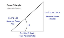
Power Factor: Power factor (pf) is defined as the ratio of active power to the apparent power of the system  i.e. pf = kWh/kVAh 

As shown in Fig, the quantities P, Q and S are represented by a power triangle.


Ideally the power factor is required to be unity. However, the power factor is leading if the load is predominantly capacitive and lagging if the load is predominantly inductive. PF incentives are given on electricity bill if the Power Factor is between 0.95 to 1. On other hand, penalties are levied if the Power Factor is below 0.9. It is therefore required that consumer should maintain higher power factor above 0.95 through proper compensation.


Power factor ratio is also equal to the cosine of the phase angle between true power and apparent  power. It should be noted that power factor, like all ratio measurements, is a unitless quantity.

As can be seen from the figure above, “power factor” can also be defined as the cosine of the electrical angle between the voltage and current vectors in an AC electrical circuit. However, power factor is not dependent upon the magnitude of the voltage and current but the phase angle between the voltage and current vectors.

The active power (kWh) is actually consumed by the electrical equipment and converted into work for creating heat, light, motion etc. However the reactive power (kVArh) is just used to provide the electromagnetic field in the inductive equipment, stored up in the windings of the equipment. Therefore while the kWh power is actually put to work, the kVArh power is just required to convert the electrical power into work.

Two Part Tariff:-

Generally, the two-part tariff is followed by distribution utilities for the billing of electrical energy. The two parts are – fixed charges based on installed capacity and variable charge which is based on energy utilized actually.


Further, the two additional components namely Electrically Duty which is usually some % of billed energy and Fuel Cost Adjustment (FCA) charges are included in the bill. Thus, the total billed amount is calculated as follows- 16% – Example value

What is kWh billing system:-

At present, in Maharashtra and  some states, the consumers are billed on Active Energy Consumption measured in kWh along with other components such as ED and FCA described above.

In kWh billing system, the incentives/ penalties are levied on Power Factor.

What is  kVAh Billing System:-

Electric power has two components – active power (kWh) and reactive power (kVArh). The active and reactive power components combine to form the apparent power (kVAh). The apparent power can be calculated as a Pythagoras sum of active power (kWh) and reactive power (kVArh).

In kVAh based billing system, the fixed charges or demand charges are levied on apparent power (kVA) and energy charges are levied on apparent energy (kVAh).
Because of kVAh billing system, Real and Reactive energies need not be charged separately.
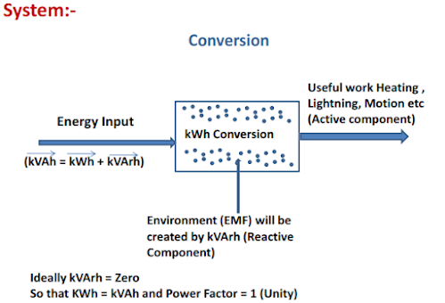

Utilization of energies 


Necessity of kVAh billing:-

Both Active (kWh) and Reactive (kVArh) energies are consumed simultaneously. Reactive Energy (kVArh) occupies the capacity of electricity network and reduces the useful capacity of system for generation and distribution & hence its consumption also needs to be billed. kWh based billing is associated with PF incentive /penalty mechanism. Considering that the kVAh based billing has an inbuilt incentive /penalty mechanism and separate mechanism for the same is no more required; instead of billing two energies separately, billing of kVAh energy is preferred as a commercial inducement.

The consumer is encouraged to draw/inject minimum reactive power.

Implementation of kVAh billing system:-

State Electricity Regulatory Commissions in various States viz. Himachal Pradesh, Delhi, Uttar Pradesh, Jammu & Kashmir, Andhra Pradesh, Chhattisgarh, Bihar, Haryana, Punjab etc. have already introduced kVAh based tariff for various categories.

In the state of Maharashtra, as per MERC Order in Case no. 195 of 2017 dated September 12, 2018, The Commission intends to implement kVAh billing to all HT consumer and LT consumers having load above 20 kW from 1st April 2020.

Advantages of kVAh billing system:-

Advantages to consumer:-

  1. kVAh billing will ensure that the consumers who will utilize the power efficiently will be paying less energy charges as compared to others who are not using the power efficiently.
  2. The new billing methodology will be much simpler to understand as number of parameters viz. PF, rkVAh (lead/lag), kWh units) will be reduced.

Advantages to utility:-

  1. Good system stability, improved power quality, improved voltage profile and reduced capital expenditure.
  2. Complete recovery of cost of active and reactive powers.
  3. Zero/ minimal drawl of reactive power by consumers.
  4. Reduction in power purchase cost

Thus, considering the larger benefit of consumers as well as the utility, it is important that the existing billing regime can be migrated to kVAh based billing.

Comparison between kWh and kVAh billing systems:-


Source - MSEDCL Presentation on KVAH

Tuesday 7 July 2020

BASIC ELECTRICAL SAFETY AND RELIABILITY AT HOSPITALS


There are several reasons why electrical safety and reliability is of uttermost importance for medical facilities.These include among others: 

  • Electromagnetic Compatibility: The high density of electric and electronic equipment in  medical premises involves a risk on electromagnetic disturbances between the electricity supply and medical devices.
  • Criticality of continuity: Many medical treatments cannot be interrupted even for a moment without entailing risk for patient and on occasion, life-threatening risk. 
  • Data integrity: Accurate medical data is essential and are often gathered by long-term or invasive patient examination. 
  • Leakage currents: Currents leaking from various devices may be individually safe but combined with others can add up quickly and exceed the safe level. 
  • Weak or sensitive patients: Some patients have weakened or non-existing reflexes in the event of direct contact with live electrical parts. Other patients may have reduced skin resistance because of stress, sweating, or catheters/electrodes introduced on or into the body. 
ENSURING SAFETY: STANDARD IEC 60364-7-710 

All low voltage electrical installations must comply with IEC 60364, the general international standard for electrical safety. In particular, Section 710 of this standard is dedicated to medical locations and prescribe certain additional requirements for such locations. It is included in the seventh part of IEC 60364, hence the code IEC 60364-7-710. Most national regulations on electrical safety in medical facilities are derived from IEC 60364-7-710. It applies to hospitals, medical clinics (including the self-contained type), medical and dental surgical facilities, dedicated rooms in nursing homes where patients are given medical treatment, rooms for physiotherapy, beauty centers, ambulatory and emergency aid units in industrial or sport facilities and veterinary surgeries. It is primarily a safety standard, as well as providing some rules on ensuring availability.

Standard IEC 60364-7-710 categorizes all medical rooms into three groups, based primarily upon the use of applied parts. An applied part is any part of an electro-medical device that might come into contact with a patient. Each group has a dedicated set of protective measures. 

Group 1 includes all rooms where the loss of power supply may endanger the patient’s life. It also includes all medical locations in which applied parts are used for intra-cardiac procedures (risk of micro-shock to cardiac muscles). Finally, it includes all rooms related to operations involving general anesthesia: pre-operation rooms, operating theaters, surgical plaster rooms, and post-operative recovery rooms. 

The measures for Group 1 include: 
  • Protection against direct contact through proper insulation
  • No power interruption is allowed (for medical equipment nor for support services such as lighting)
  • An IT earthing system to protect against earth faults (avoiding power interruptions) 
Group 2 includes all medical locations that do not belong to Group 2 and where applied parts are used,
externally or invasively. Examples are rooms serving for physiotherapy or hydrotherapy, and dental surgery.

The measures for Group 2 include:

  • Protection against direct contact through proper insulation
  • In case of a power interruption, crucial support services such as lighting should switch to an alternative power supply
  • A TNS earthing system is permitted 
Group 3 includes all medical locations where no applied parts are used, such as outpatient rooms, massage rooms without electro-medical devices, offices, store rooms, canteens, changing rooms, corridors, staff hygiene facilities, waiting rooms, et cetera. No extra measures have to be taken for Group 3 other than those general prescriptions for electrical safety in buildings (Standard IEC 60364). Nevertheless, a high level of electrical reliability and safety should be maintained. This means that power quality disturbances (e.g. harmonic distortion, stray currents, et cetera), electric faults, and equipment damage (e.g. neutral conductor interruption, insulation degradation, et cetera) should be avoided. If a TN or TT earthing system is being used, it is advisable to continuously monitor the insulation quality by a Residual Current Monitor (RCM). This device should not be confused with a Residual Current Device (RCD). The RCM monitor can never disconnect the circuit, but rather continuously monitors the differential current value and sends alarm signals if thresholds are exceeded. This enables taking predictive measures and avoiding unexpected failures. Such monitoring can also
be a first step in improving the energy efficiency of the system. 

Qualified medical personnel must carry out the assignment of the rooms to one of these three groups. If no such personnel are available, the national healthcare organization must be called in. 

The function of a particular room is often changed during the lifetime of a hospital; for instance because of changed needs. It can therefore be wise to equip certain rooms for a higher group classification than their initial use demands. Those rooms will then be upgradable without significant costs for the electrical installation. 


Source: European Cu Institute


Friday 3 July 2020

Minimal set characteristics of a Battery based Storage System

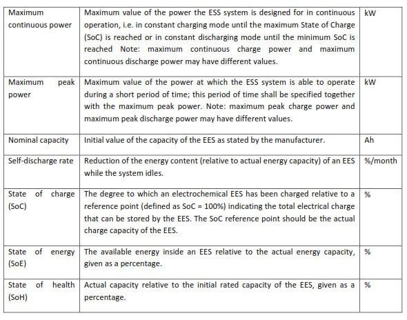
Any grid connected storage system can be seen as a so-called black box with certain measures of performance (MoP). The definition of the MoP is the same for every kind of storage system regardless of what’s inside the black box, but the technology and design choices of a particular system determine their value. 

The table below lists a minimal set of characteristics of a battery based storage system; it is a subset of the definitions in the GRIDSTOR RP document (1). The definitions from IEC 62933-1 CDV are used (9) for electrical energy storage systems.


Source:European Copper Institute.

Wednesday 1 July 2020

Types of Power System Stability and Stability Studies benefits

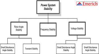
Power system stability is the ability of the system, for a given initial operating condition, to regain a normal state of equilibrium after being subjected to a disturbance.   The ability of the power system to return to its normal or stable conditions after being disturbed is called stability. Disturbances of the system may be of various types like sudden changes of load, the sudden short circuit between line and ground, line-to-line fault,  all three line faults, switching, etc.


The stability of the system mainly depends on the behaviour of the synchronous machines after a disturbance. The stability of the power system is mainly divided into two types depending upon the magnitude of disturbances

Steady state stability
Transient stability

Steady-state stability – It refers to the ability of the system to regain its synchronism (speed & frequency of all the network are same) after slow and small disturbance which occurs due to gradual power changes. Steady-state stability is subdivided into two types

Dynamic stability – It denotes the stability of a system to reach its stable condition after a very small disturbance (disturbance occurs only for 10 to 30 seconds). It is also known as small signal stability. It occurs mainly due to the fluctuation in load or generation level.

Static stability – It refers to the stability of the system that obtains without the aid (benefit) of automatic control devices such as governors and voltage regulators.

Transient Stability – It is defined as the ability of the power system to return to its normal conditions after a large disturbance. The large disturbance occurs in the system due to the sudden removal of the load, line switching operations; fault occurs in the system, sudden outage of a line, etc.

Transient stability is conducted when new transmitting and generating system are planned. The swing equation describes the behaviour of the synchronous machine during transient disturbances.

The transient and steady-state disturbances occur in the power system are shown in the graph below. These disturbances reduce the synchronism of the machine, and the system becomes unstable.

Stability studies are helpful for the determination of critical clearing time of circuit breakers, voltage levels and a transfer capability of the systems.


Monday 15 June 2020

2022-23 to be golden period for global EV industry

As per Frost and Sullivan, 2022-23 will be the golden period for EVs with the number of launches increasing significantly and battery prices coming down which would provide a very vital impetus to the growth of the global EV industry.


By 2025, 30-35 percent of sales are expected to be electric which includes mild hybrid, full hybrids, plug-in, and battery. In terms of battery electric vehicles, about 10-12 percent of global sales will be fully electric.

Its  said that the mild hybrid systems especially 12Volt systems, 48Volt systems, and 12+12 volt systems could be very attractive options for markets like China and India, especially in the small-to-medium segment.

NEWS: Karnataka to open roads for electric two-wheeler taxis

The Karnataka government on Thursday proposed using electric two-wheelers as taxis on Bengaluru roads, potentially leapfrogging regulations around using petrol-powered bikes as taxis in the state.

In the budget, the state proposed implementing an electric bike taxi project to improve last mile connectivity of public transportation, without divulging details.

“To improve the last mile connectivity in public transport in Bengaluru, it is proposed to implement “Electric Bike Taxi” project,” it said in the budget for financial year 2020-21.

Introducing regulations to allow use of two-wheelers as taxis has been a longstanding demand of mobility platforms such as Rapido, Ola and Uber. However, the state has delayed the rules despite getting approval from the Centre.

While some players in the bike taxi space dubbed Karnataka’s proposal as revolutionary, they said they would wait for details before commenting on its viability.

Others said the proposal would be hard to pull off in the near term, given a lack of electric two-wheelers on the roads today.

Uber and Ola, which currently offer bike taxi services in some cities, declined to comment for the story. Rapido, the largest bike taxi service in the country, could not be reached for comment.

“The biggest reason bike taxis worked was that a person who had a scooter or motorbike could now make money ferrying people,” said Vivekananda Hallekere, co-founder and CEO of Bounce, a two-wheeler rentals startup. “The proposal by Karnataka would mean that people will need to start buying electric scooters and I don’t know how successful that would be.”

The current model of bike taxis where bike owners attach themselves to platforms will not work under Karnataka’s proposal, but it could lead to mobility firms building their own fleets of two-wheeler EVs, he said.


Source: Economic Times