Friday 28 December 2018

Battery Hazards and its Reasons


There are four main hazards associated with batteries

A. Battery acid: The electrolyte in a battery is corrosive and can burn skin or eyes, eat holes in clothing, or even etch a concrete floor. 

B. Flammable gases: Batteries emit hydrogen gas, which is flammable. It ignites easily and can cause a fire or explosion if allowed to accumulate in a small area. 

C. Electrical shock: Many of us are aware of this danger because we may have seen sparks fly when jumper cables are attached to a car battery. 

D. Weight: Batteries, like those used in forklifts, are heavy and require proper material handling equipment to lift them safely. 2. To protect themselves when working with

Safe Operation of Batteries

Because batteries store large amounts of energy, there are certain hazards that are associated with battery operation. These hazards must be fully understood to ensure safe operation of batteries.

Shorted Cell

Cell short circuits can be caused by several conditions, which include the following:

  1. Faulty separators
  2. Lead particles or other metals forming a circuit between the positive and negative plates
  3. Buckling of the plates or
  4. Excessive sediments in the bottom of the jar.


The primary cause of some of these occurrences is overcharging and over discharging of the battery, which causes sediment to build up due to flaking of active material and buckling of cell plates.

🔘Overcharging and over discharging of batteries should be avoided at all costs. Short circuits cause a great reduction in battery capacity. With each shorted cell, battery capacity is reduced by a percentage equal to one over the total number of cells.


Gas Generation

A lead-acid battery cannot absorb all the energy from the charging source when the battery is nearing the completion of the charge.

This excess energy dissociates water by way of electrolysis into hydrogen and oxygen. Oxygen is produced by the positive plate, and hydrogen is produced by the negative plate.

This process is known as gassing. Gassing is first noticed when cell voltage reaches 2.30-2.35 volts per cell and increases as the charge progresses.
At full charge, the amount of hydrogen produced is about one cubic foot per cell for each 63 ampere-hours input. If gassing occurs and the gases are allowed to collect, an explosive mixture of hydrogen and oxygen can be readily produced. It is necessary, therefore, to ensure that the area is well ventilated and that it remains free of any open flames or spark-producing equipment.

As long as battery voltage is greater than 2.30 volts per cell, gassing will occur and cannot be prevented entirely. To reduce the amount of gassing, charging voltages above 2.30 volts per cell should be minimized (e.g., 13.8 volts for a 12 volt battery).


Battery Temperature

The operating temperature of a battery should preferably be maintained in the nominal band of 60-80°F. Whenever the battery is charged, the current flowing through the battery will cause heat to be generated by the electrolysis of water.

The current flowing through the battery (I) will also cause heat to be generated (P) during charge and discharge as it passes through the internal resistance (Ri), as illustrated using the formula for power in equation below:

P=I^2 Ri

Higher temperatures will give some additional capacity, but they will eventually reduce the life of the battery. Very high temperatures, 125°F and higher, can actually do damage to the battery and cause early failure.
Low temperatures will lower battery capacity but also prolong battery life under floating (i.e., slightly charging) operation or storage. Extremely low temperatures can freeze the electrolyte, but only if the battery is low in specific gravity.

Conclusion

Battery hazards are summarized below. Battery Hazards Summary Short circuits cause a great reduction in battery capacity.

To prevent short circuits in a battery, overcharging and over discharging should be avoided at all costs. The adverse effect of gassing is that if gassing occurs and the gases are allowed to collect, an explosive mixture of hydrogen and oxygen can be readily produced.

To reduce the amount of gassing, charging voltages above 2.30 volts per cell should be minimized. Whenever the battery is charged, the current flowing through the battery will cause heat to be generated by the electrolysis of water and by I2Ri power generation.

Higher temperatures will give some additional capacity, but they will eventually reduce the life of the battery. Very high temperatures, 125°F and higher, can actually do damage to the battery and cause early failure.

Monday 10 December 2018

Consequences of high harmonic distortion levels

The total harmonic distortion(THD) is a measurement of the harmonic distortion present in a signal and is defined as the ratio of the sum of the powers of all harmonic components to the power of the fundamental frequency. Distortion factor, a closely related term, is sometimes used as a synonym.

The plant engineer’s worst fear…

Just as high blood pressure can create stress and serious problems in the human body, high levels of harmonic distortion can create stress and resultant problems for the utility’s distribution system and the plant’s distribution system, as well as all of the equipment that is serviced by that distribution system.


The result may be the plant engineer’s worst fear – the shutting down of important plant equipment ranging from a single machine to an entire line or process.


Equipment shutdown can be caused by a number of events. As an example, the higher voltage peaks that are created by harmonic distortion put extra stress on motor and wire insulation, which ultimately can result in insulation breakdown and failure. In addition, harmonics increase rms current, resulting in increased operating temperatures for many pieces of equipment, greatly reducing equipment life.

Table below summarises some of the negative consequences that harmonics can have on typical equipment found in the plant environment.


Negative Consequences of Harmonics on Plant Equipment


While these effects are categorised by problems created by current and voltage harmonics, current and voltage harmonic distortion usually exist together (current harmonic distortion causes voltage harmonic distortion) .

"Harmonic distortion disrupts plants. Of greatest importance is the loss of productivity, throughput, and, possibly, sales"

These occur because of process shutdowns due to the unexpected failure of motors, drives, power supplies, or just the spurious tripping of breakers. Plant engineers realize how costly downtime can be and pride themselves in maintaining low levels of plant downtime. In addition, maintenance and repair budgets can be severely stretched.

For example, every 10°C rise in the operating temperatures of motors or capacitors can cut equipment life by 50%.

Thursday 4 October 2018

How Really Motor Works?!

The AC motor commonly consists of two basic parts, an outside stator having coils supplied with alternating current to produce a rotating magnetic field, and an inside rotor attached to the output shaft producing a second rotating magnetic field. The rotor magnetic field may be produced by permanent magnets, reluctance saliency, or DC or AC electrical windings.


Less common, AC linear motors operate on similar principles as rotating motors but have their stationary and moving parts arranged in a straight line configuration, producing linear motion instead of rotation.

The basic working of a motor is based on the fact that when ‘a current carrying conductor is placed in a magnetic field, it experiences a force’.

Figure 1 - A motor action

If you take a simple DC motor, it has a current-carrying coil supported in between two permanent magnets (opposite pole facing) so that the coil can rotate freely inside. When the coil ends are connected to a DC source then the current will flow through it and it behaves like a bar magnet, as shown in Figure 1.

As the current starts flowing, the magnetic flux lines of the coil will interact with the flux lines of the permanent magnet.

This will cause a movement of the coil (Figures 1a, 1b, 1c, 1d) due to the force of attraction and repulsion between two fields. The coil will rotate until it achieves the 180° position, because now the opposite poles will be in front of each other (Figure 1e) and the force of attraction or repulsion will not exist.

The role of the commutator: The commutator brushes just reverse the polarity of DC supply connected to the coil. This will cause a change in the direction of the current of the magnetic field and start rotating the coil by another 180° (Figure 1f).

The brushes will move on like this to achieve continuous coil rotation of the motor.
Similarly, the AC motor also functions on the above principle; except here, the commutator contacts remain stationary, because AC current direction continually changes during each half-cycle (every 180°).

Thursday 27 September 2018

Impact of Voltage Dip on Power Quality

A voltage sag or voltage dip is a short duration reduction in rms voltage which can be caused by a short circuit, overload or starting of electric motors. A voltage sag happens when the rms voltage decreases between 10 and 90 percent of nominal voltage for one-half cycle to one minute.

Its also explained as short, temporary drop in the voltage magnitude in the distribution or customer's electrical system. It may be caused by various faults in the transmission and distribution networks, faults in the connected equipment or high inrush and switching currents in the customer's installation.

What is causing voltage dips?

Figure 1 shows the sketch of a voltage dip, together with the associated definitions. The major cause of voltage dips on a supply system is a fault on the system, that is sufficiently remote electrically that a voltage interruption does not occur.

Other sources are the starting of large loads (especially common in industrial systems), and, occasionally, the supply of large inductive loads.
Figure 1 - Voltage dip sketch

Voltage dips due to the latter are usually due to poor design of the network feeding the consumer. A voltage dip is the most common supply disturbance causing interruption of production in an industrial plant.

Faults on a supply network will always occur, and in industrial systems, it is often practice to specify equipment to ride-through voltage dips of up to 0.2s. The most common exception is contractors, which may well drop out if the voltage dips below 80% of rated voltage for more than 50-100ms.

Motor protection relays that have an under voltage element setting that is too sensitive is another cause. Since contactors are commonly used in circuits supplying motors, the impact of voltage dips on motor drives, and hence the process concerned, requires consideration.

Figure 2: multiple-voltage-dip emerich

Other network-related fault causes are weather–related (such as snow, ice, wind, salt spray, dust) causing insulator flash over, collisions due to birds, and excavations damaging cables. Multiple voltage dips, as illustrated in Figure 2, cause more problems for equipment than a single isolated dip.

The impact on consumers may range from the annoying (non-periodic light flicker) to the serious (tripping of sensitive loads and stalling of motors). Where repeated dips occur over a period of several hours, the repeated shutdowns of equipment can give rise to serious production problems.

Figure 3 shows an actual voltage dip, as captured by a Power Quality recorder.

Figure 3 - Recording of a voltage dip


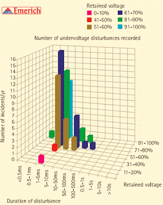
Typical data for under voltage disturbances on power systems during evolving faults are shown in Figure 4.


Figure 4 - Under voltage disturbance histogram

Disturbances that lie in the front right-hand portion of the histogram are the ones that cause most problems


Wednesday 26 September 2018

Electrical Load & Types


An electrical load is a device or an electrical component that consumes electrical energy and convert it into another form of energy. Electric lamps, air conditioners, motors, resistors etc. are some of the examples of electrical loads. They can be classified according to various different factors. 


Classifications of electrical loads:

Resistive, Capacitive, Inductive
Electrical loads can be classified according to their nature as Resistive, Capacitive, Inductive and combinations of these.

Resistive Load
Two common examples of resistive loads are incandescent lamps and electric heaters.

Resistive loads consume electrical power in such a manner that the current wave remains in phase with the voltage wave. That means, power factor for a resistive load is unity.

Capacitive Load
A capacitive load causes the current wave to lead the voltage wave. Thus, power factor of a capacitive load is leading.

Examples:  capacitor banks, buried cables, capacitors used in various circuits such as motor starters etc.

Inductive Load
An inductive load causes the current wave to lag the voltage wave. Thus, power factor of an inductive load is lagging.
Example: Transformers, motors, coils etc.

Combination Loads
Most of the loads are not purely resistive or purely capacitive or purely inductive. Many practical loads make use of various combinations of resistors, capacitors and inductors. Power factor of such loads is less than unity and either lagging or leading.

Examples: Single phase motors often use capacitors to aid the motor during starting and running, tuning circuits or filter circuits etc.

Types Of Loads In Power System

Domestic load: 

It consists of lights, fans, home electric appliances (including TV, AC, refrigerators, heaters etc.), small motors for pumping water etc. Most of the domestic loads are connected for only some hours during a day. For example, lighting load is connected for few hours during night time.

Commercial Load:

Commercial load consists of electrical loads that are meant to be used commercially, such as in restaurants, shops, malls etc. This type of load occurs for more hours during the day as compared to the domestic load.

Industrial Load:

Industrial load consists of load demand by various industries. It includes all electrical loads used in industries along with the employed machinery. Industrial loads may be connected during the whole day.

Municipal Load:
This type of load consists of street lighting, water supply and drainage systems etc. Street lighting is practically constant during the night hours. Water may be pumped to overhead storage tanks during the off-peak hours to improve the load factor of the system.

Irrigation Load:

Motors and pumps used in irrigation systems to supply the water for farming come under this category. Generally, irrigation loads are supplied during off-peak or night hours.

Traction Load:
Electric railways, tram cars etc. come under traction loads. This type of loads reaches its peak during morning and evening hours.

Some Other Classifications Of Electrical Loads

According To Load Nature
  • Linear loads
  • Non-linear loads

According To Phases
  • Single phase loads
  • Three phase loads

According To Importance
  • Vital electrical loads (e.g. required for life safety)
  • Essential electrical loads
  • Non-essential / normal electrical loads

Electrical loads may also be classified in may different manners, such as according to their functions.

HVDC Technology for Transmitting Electricity

High Voltage direct current (HVDC) technology

An alternate means of transmitting electricity is to use high-voltage direct current (HVDC) technology. As the name implies, HVDC uses direct current to transmit power. Direct current facilities are connected to HVAC systems by means of rectifiers, which convert alternating current to direct current, and inverters, which convert direct current to alternating current.

"Early applications used mercury arc valves for the rectifiers and inverters but, starting in the 1970s, thyristors became the valve type of choice"

Thyristors are controllable semiconductors that can carry very high currents and can block very high voltages. They are connected is series to form a thyristor valve, which allows electricity to flow during the positive half of the alternating current voltage cycle but not during the negative half.

"Since all three phases of the HVAC system are connected to the valves, the resultant voltage is unidirectional but with some residual oscillation. Smoothing reactors are provided to dampen this oscillation"

🔺 HVDC transmission lines can either be single pole or bipolar, although most are bipolar, that is, they use two conductors operating at different polarities such as +/-500 kV.

HVDC submarine cables are either of the solid type with oil-impregnated paper insulation or of the self-contained oil-filled type. New applications also use cables with extruded insulation, cross-linked polyethylene. Although synchronous HVAC transmission is normally preferred because of its flexibility, historically there have been a number of applications where HVDC technology has advantages:

1 The need to transmit large amounts of power (>500 mW) over very long distances ( >500 km), where the large electrical angle across long HVAC transmission lines (due to their impedances) would result in an unstable system.

🔺 Examples of this application are the 1,800 mW ABC Project, where the transmission delivers the power to approximately 930 km away; the 3,000 mW system from the Three Gorges project to Shanghai in China, approximately 1,000 km distant; and the 1,456 km long, 1,920 mW line from the Cabora Bassa project in Mozambique to Apollo, in South Africa. In the United States the 3,100 mW Pacific HVDC Intertie (PDCI) connects the Pacific Northwest (Celilo Converter Station) with the Los Angeles area (Sylmar Converter Station) by a 1,361 km line.

2. The need to transmit power across long distances of water, where there is no method of providing the intermediate voltage compensation that HVAC requires. 

3. When HVAC interties would not have enough capacity to withstand the electrical swings that would occur between two systems. 

4. The need to connect two existing systems in an asynchronous manner to prevent losses of a block of generation in one system from causing transmission overloads in the other system if connected with HVAC. 

5.  Connection of electrical systems that operate at different frequencies. These applications are referred to as back-to-back ties. An example is HVDC ties between England and France.

6 Provision of isolation from short-circuit contributors from adjacent systems since dc does not transmit short-circuit currents from one system to another.

There is increasing interest in the use of HVDC technology to facilitate the new markets.

HVDC provides direct control of the power flow and is there-fore a better way for providing contractual transmission services. Some have suggested that dividing the large synchronous areas in the United States into smaller areas interconnected by HVDC will eliminate coordination problems between regions, will provide better local control, and will reduce short-circuit duties, significantly reducing costs.

Monday 24 September 2018

Emerich Motivation - Change your mind and the rest will follow!

All change starts with a change of mind. You have to start by changing your thoughts about want you want to change. 


"Progress is impossible without change, and those who cannot change their minds cannot change anything. - GEORGE BERNARD SHAW 

Change has a very negative connotation for most people. On a deep emotional level we are creatures of comfort and we automatically seek out that which feels good in the moment. We long for comfort and this usually comes from that which we know; that which is familiar to us. Once we can comfortably deal with and "know" all the "unknowns" we can "relax" –because your nervous system and your mind is designed to find and attach a meaning(s) to everything and therefore something new is always a confrontation between that which is and that which will be in your mind. 

The unknown is always something that your mind and your nervous system has to "unravel" afresh and this very process feels uncomfortable on many levels. When something becomes comfortable you get used to it as you remove all the "unknowns" and your automatic behaviour can take over again. 

Our nervous system works primarily by conditioning and by repetition we notice and assume patterns that are consistent. This system is really there to serve us in helping us being more efficient and to be able to do more, more efficiently. Your mind is designed to always look for the best way. Through repetition we learn certain orders and sequences in which things happen and we learn to
recognise and respond according to these sequences.

Every emotion you experience, for instance, is nothing but the result of a sequence of events and reactions triggered by your unconscious awareness that generates and creates the actual feeling which is nothing but a sensation in your nervous system.

To change anything you must first of all become aware of these patterns. You must become aware of what goes on under the surface of your conscious awareness. This is not difficult and everybody can do this. You need not understand everything about the human nervous system to use it. Simply be
aware of the fact that there is a part of you that responds and acts "automatically" based on your past experiences and associations. 

The challenge is to go from one pattern, one that does not serve you, to one which does. You quite literally would have to change your mind in that you have to change the way you perceive yourself and your life. Doing things differently will feel uncomfortable at first, but you can rest assured that the "uncomfortable" will become "comfortable" as you start to form new associations and new patterns of association. 

The process of making the "uncomfortable" comfortable or making the "unknown" known is the way we grow as human beings. What you are comfortable with represents your comfort zone which includes all the experiences that you can comfortably deal with. If you don't expand this "zone" then you simply won't expand yourself as a person. The need to grow and become more as a person, is a deep emotional need that all humans have. Without growth you simply won't be happy. 

All growth, although it feels uncomfortable in the moment always feels immensely fulfilling in the long term and it is this feeling that we all really crave for; the feeling that we call "good". You can do something that feels comfortable and "good" in the moment by staying with what you know, but true fulfilment
comes from pushing beyond your comfort zone and creating a sense of pride in yourself. Growth means change and change involves risk and risk is the process of stepping from the known to the unknown. The truth is that all of life is constantly in a process of change. Nothing ever stays the same.

It is the nature of all of life, including you! Even if you do nothing life will still change. For you to progress, you have to decide to consciously initiate and create the change. You have to consciously put yourself in the uncomfortable place where you can grow and as you do this you progress. Progress is by choice while change is automatic. To be in control of your life you have to consciously choose to change and to keep changing yourself to become the person you want to be. All change starts with a change of mind. You have to start by changing your thoughts about want you want to change. 

In changing the way you think about something you immediately change your perception and consequently the way you feel about it. When you change the way you feel you change your behaviour and that is how you progress. Constantly trying to change behaviour will rarely create long term and lasting change. Change your mind and the rest will follow! If you don't change then you simply won't grow and if you don't grow you are not really living.

Electric Potential and Potential Difference

Potential difference is the term used to describe how large the electrostatic force is between two charged objects. If a charged body is placed between two objects with a potential difference, the charged body will try to move in one direction, depending upon the polarity of the object.

If an electron is placed between a negatively-charged body and a positively-charged body, the action due to the potential difference is to push the electron toward the positively-charged object.

The electron, being negatively charged, will be repelled from the negatively-charged object and attracted by the positively-charged object, as shown in Figure 1.
Fig-1: potential difference between two charged objects

Due to the force of its electrostatic field, these electrical charges have the ability to do work by moving another charged particle by attraction and/or repulsion.

This ability to do work is called “potential”; therefore, if one charge is different from another, there is a potential difference between them. The sum of the potential differences of all charged particles in the electrostatic field is referred to as electromotive force (EMF).

The basic unit of measure of potential difference is the “volt“. The symbol for potential difference is “V” indicating the ability to do the work of forcing electrons to move.

Because the volt unit is used, potential difference is also called “voltage”

Voltage

The basic unit of measure for potential difference is the volt (symbol V), and, because the volt unit is used, potential difference is called voltage . An object’s electrical charge is determined by the number of electrons that the object has gained or lost. Because such a large number of electrons move, a unit called the “coulomb” is used to indicate the charge. One coulomb is equal to 6.28 x 10¹⁸ (billion, billion) electrons.

For example, if an object gains one coulomb of negative charge, it has gained 6,280,000,000,000,000,000 extra electrons. A volt is defined as a difference of potential causing one coulomb of current to do one joule of work.

A volt is also defined as that amount of force required to force one ampere of current through one ohm of resistance. The latter is the definition with which we will be most concerned in this module.

Source: Web based Article about Electric Potential

Friday 21 September 2018

Sources of Sound / Noise in Transformers

Humming and buzzing noises are a common complaint with electrical transformers, which are a common sight in both industrial and residential areas. Even though a transformer has no moving parts, these vibration-like sounds are quite similar to those produced by generators and motors.

The main cause of transformer noise is the Magnetostriction Effect. This is where the dimensions of ferromagnetic materials change upon contact with a magnetic field. The alternation current that flows through an electrical transformer’s coils has a magnetic effect on its iron core. It causes the core to expand and contract, resulting in a humming sound.

Low Frequencies

Unlike cooling-fan or pump noise, the sound radiated from a transformer is tonal in nature, consisting of even harmonics of the power frequency. It is generally recognised that the predominant source of transformer noise is the core.

The low frequency, tonal nature of this noise or buzzing makes it harder to mitigate than the broadband higher frequency noise that comes from the other sources.

🔺 This is because low frequencies propagate farther with less attenuation. Also, tonal noise can be perceived more acutely than broadband levels, even with high background noise levels. This combination of low attenuation and high perception makes tonal noise the dominant problem in the neighbouring communities around transformers.

To address this problem, most noise ordinances impose penalties or stricter requirements for tonal noise.

Even though the core is the principal noise source in transformers, the load noise, which is primarily caused by the electromagnetic forces in the windings, can also be a significant influence in low-sound-level transformers. The cooling equipment (fans and pumps) noise typically dominates the very low-and very high-frequency ends of the sound spectrum, whereas the core noise dominates in the intermediate range of frequencies between 100 and 600 Hz.

These sound-producing mechanisms can be further characterised as follows.


Core Noise

When a strip of iron is magnetized, it undergoes a very small change in its dimensions (usually only a few parts in a million).

🔺 This phenomenon is called magnetostriction.

The change in dimension is independent of the direction of magnetic flux; therefore, it occurs at twice the line frequency. Because the magnetostriction curve is nonlinear, higher harmonics of even order also appear in the resulting core vibration at higher induction levels (above 1.4 T).

Flux density, core material, core geometry, and the wave form of the excitation voltage are the factors that influence the magnitude and frequency components of the transformer core sound levels. The mechanical resonance in transformer mounting structure as well as in core and tank walls can also have a significant influence on the magnitude of transformer vibrations and, consequently, on the acoustic noise generated.

Load Noise

Load noise is caused by vibrations in tank walls, magnetic shields, and transformer windings due to the electromagnetic forces resulting from leakage fields produced by load currents. These electromagnetic forces are proportional to the square of the load currents.

🔺 The load noise is predominantly produced by axial and radial vibration of transformer windings.

However, marginally designed magnetic shielding can also be a significant source of sound in transformers. A rigid design for laminated magnetic shields with firm anchoring to the tank walls can greatly reduce their influence on the overall load sound levels.

The frequency of load noise is usually twice the power frequency. An appropriate mechanical design for laminated magnetic shields can be helpful in avoiding resonance in the tank walls. The design of the magnetic shields should take into account the effects of overloads to avoid saturation, which would cause higher sound levels during such operating conditions.

Studies have shown that except in very large coils, radial vibrations do not make any significant contribution to the winding noise.

The compressive electromagnetic forces produce axial vibrations and thus can be a major source of sound in poorly supported windings. In some cases, the natural mechanical frequency of winding clamping systems may tend to resonate with electromagnetic forces, thereby severely intensifying the load noise. In such cases, damping of the winding system may be required to minimize this effect. The presence of harmonics in load current and voltage, most especially in rectifier transformers, can produce vibrations at twice the harmonic frequencies and thus a sizeable increase in the overall sound level of a transformer.

Through several decades, the contribution of the load noise to the total transformer noise has remained moderate.

However, in transformers designed with low induction levels and improved core designs for complying with low sound-level specifications, the load-dependent winding noise of electromagnetic origin can become a significant contributor to the overall sound level of the transformer.

In many such cases, the sound power of the winding noise is only a few dB below that of the core noise.

Fan and Pump Sound

Power transformers generate considerable heat because of the losses in the core, coils, and other metallic structural components of the transformer. This heat is removed by fans that blow air over radiators or coolers. Noise produced by the cooling fans is usually broadband in nature.

🔺 Cooling fans usually contribute more to the total noise for transformers of smaller ratings and for transformers that are operated at lower levels of core induction.

Factors that affect the total fan noise output include tip speed, blade design, number of fans, and the arrangement of the radiators.

Resistors in detail


Resistors are one of the simplest varieties of electronic components. A resistor is a two-terminal device that has a fixed relationship between the current passing through the device and the voltage drop across the device.


This relationship is described in Ohm’s law, which states that “the strength of a direct current is directly proportional to the potential difference and inversely proportional to the resistance of the circuit” (Merriam-Webster).


This relationship is illustrated by the following equation:

Resistance formula


Where:

I = current in amps (A)
V = voltage in volts (V)
R = resistance in ohms (Ω)

Although resistors are very common and simple devices, the different composition types of resistors are often misunderstood.


There are three common resistor composition types:

Carbon resistors
Film resistors
Wirewound resistors


Carbon Resistors


Carbon resistors are the most common type of composition resistors. They are inexpensive, and serve a general purpose in electronic circuits.

Consisting of carbon particles mixed with a binder, carbon resistors are molded into a cylinder and baked. The carbon particles mixed with the binder (usually ceramic) are the resistive element, accompanied by embedded wire leads or metal end caps to which the lead wires are attached 

Carbon Film Resistors

A film resistor uses a film of carbon that is deposited (either sprayed or coated) onto a substrate, which forms the resistive element. The resistance is adjusted by cutting or shaping the film.

Wirewound Resistors


Wirewound resistors are made up of metal resistance wire (usually nichrome), and are made by winding the wire around the insulated core of the resistor. Wirewound resistors have a poor frequency response and are typically only used in low frequency applications.